

How To Read Electrician Electrical Drawings
Learn how to read electrical drawings and get easy-to-use electrical drawing software to create professional-looking electrical drawings.
How to Read A Electrical Drawing
ane. Familiarize with Standardized Electrical Symbols
Knowing the meanings of basic electrical symbols in your electrical drawing will help you quickly empathize and troubleshooting the excursion.
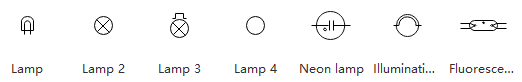
A lamp is usually represented as a circle with a cross within it. When the electric current passes through the lamp, it will produce light.
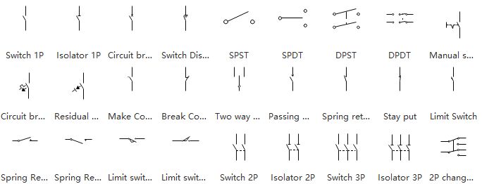
Switches are symbolized past an opening or break in the line. It looks like the flip of a light switch.
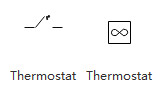
The thermostat is a kind of thermal switch that is triggered by the changes of temperature.
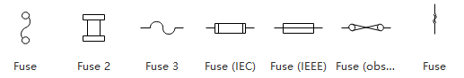
A fuse is represented by a slight zigzag in the line. Motors are displayed by bumps along the line. Information technology looks similar an "Thou" with 5 or 6 humps.
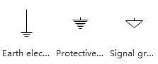
The footing is represented by either a triangle pointing downward or a set of parallel lines that get shorter as they appear below each other, in effect representing the inner area of the triangle pointing down. Ground is a common reference signal that schematics use to show the overall unity of the various functions of the circuit. Information technology does not refer to the actual ground of the earth.
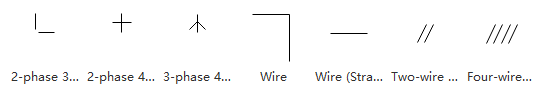
Wires are used to link the devices together. All points along the wire are identical and connected. Wires may cross each other on an electrical drawing, but that does not necessarily mean that they connect. If they do not connect, one volition be shown looping around the other in a semicircle. If they do connect, they volition cross, and a dot will exist seen at the point where the lines cross.
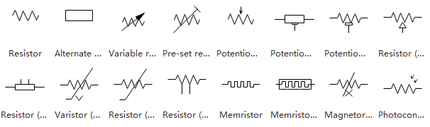
Resistors human activity to impede the flow of the excursion to an extent determined by the resistance value used. They are used to scale and shape the bespeak.
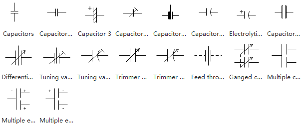
Capacitors are used to control rapidly irresolute signals, as opposed to the static or slowly irresolute signals that are conditioned by resistors. The traditional use of capacitors in modern circuits is to depict racket, which is inherently a rapidly changing signal, away from the signal of interest and drain it away to the ground.
EdrawMax
All-in-One Diagram Software
Create more than than 280 types of diagrams effortlessly
Beginning diagramming with various templates and symbols easily
- Superior file compatibility: Import and consign drawings to various file formats, such as Visio
- Cross-platform supported (Windows, Mac, Linux, Web)
2. Learn Reading Pattern
Read schematics in the design that you would read the text. With rare exceptions, schematics should be read left to right and height to bottom. The signal generated or used past the circuit will catamenia in this direction. The user can follow the same path that the signal uses to empathize what the signal does or how it is beingness modified.
iii. Place Polarity
Some components to a circuit board are polarized, meaning that one side is positive and the other negative. It means that y'all have to adhere information technology in a specified way. For well-nigh symbols, polarity is included in the symbol. To identify the polarity of the physical part, a general dominion of thumb is to notice out which metal lead wire is longer. The longer part is the + side.
4. Empathise Names and Values
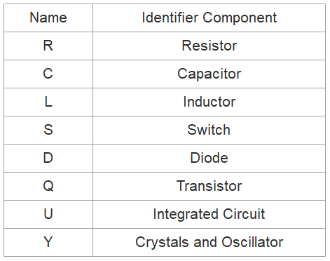
Values help define what a component is. For electrical components like resistors, capacitors, and inductors, the value tells us how many ohms, farads, or henries they accept. For other components, like integrated circuits, the value may be the name of the chip. Crystals might list their oscillating frequency as their value. The value of a schematic component calls out its nearly important characteristic.
Component names usually consist of one or two messages and a number. The letter part of the proper name represents the type of component - R's for resistors, C'due south for capacitors, U's for integrated circuits, etc. Each component name in an electrical cartoon should be unique; if you lot accept multiple resistors in a excursion, for example, they should exist named R1, R2, R3, etc.
Components' names assistance usa reference specific points in schematics. The prefixes of names are pretty well standardized. For some components, like resistors, the prefix is merely the kickoff letter of the component. Other proper name prefixes are not so literal; inductors, for example, are L's (because the current has already taken I [but it starts with a C...electronics is a empty-headed place]). Here'southward a quick table of mutual components and their name prefixes:
Electrical Drawing Example
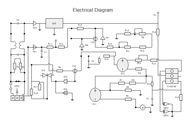
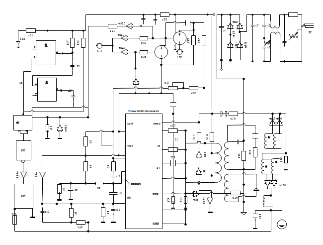
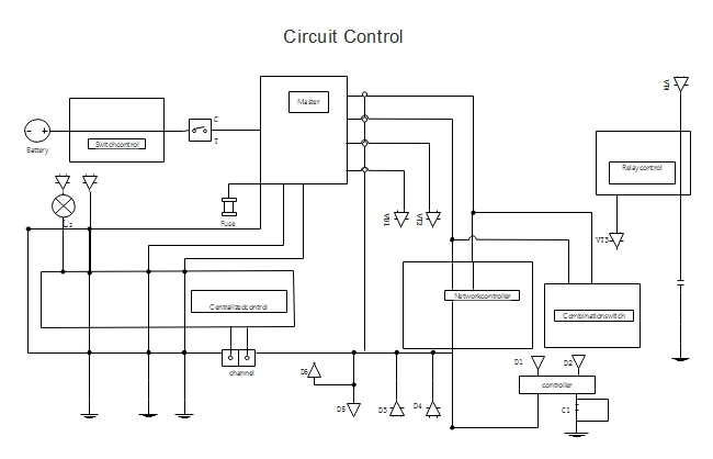
Using these above electrical symbols can help yous depict standard electrical diagrams. Adding the components' names on each symbol makes information technology easier for both beginners and professionals to understand the circuits in seconds. Here are some expert-looking electric drawing examples, and you will observe more in Edraw Template Center.
Basic Electric Diagram
Electrical Wiring Diagram
Excursion Control Diagram
How to Create an Electric Diagrams by Yourself
More Related Manufactures
Electric Diagram
Schematic Diagram
Circuits and Logic Diagram
Systems Diagram
Integrated Circuit Schematics Software
Industrial Control Systems
Process Flow Diagram
Procedure and Instrumentation Drawing
How to Draw Technology Diagram

Source: https://www.edrawsoft.com/how-to-read-electrical-drawing.html
Posted by: criglerancestright.blogspot.com
0 Response to "How To Read Electrician Electrical Drawings"
Post a Comment